Kenwood KA-6000 Solid State Stereo Amplifier
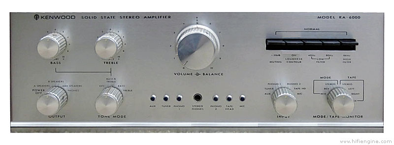
The KA-6000 was Kenwood's top of the line integrated amplifier introduced in 1969.
This little gem of an amplifier produces 45 WPC into an 8 ohm load.
An interesting thing with this amplifier is that there is only one potentiometer on the front. All of the audio controls are either rotary switches or toggle switches.
In an amplifier as old as this one, there is a good likelihood that most of the electrolytic capacitors have become leaky. If you are handy with a soldering iron, can read a schematic and are willing to do a very modest amount of work, you can probably fix this problem yourself.
This amplifier has several of the 2SC458 and 2SC871 transistors scattered throughout the amplifier. These are known for becoming nosiy as they age and potnetially causing a myriad of hard to diagnose problems down the road. If you are replacing electrolytic capacitors in the unit you should strongly consider replacing these two while you are in there. A common replacement for the 2SC871 is the KSC1845 which is avalable from a number of online electronics suppliers.
Coupling capacitors, as used in the Kenwood KA-6000 amplifier, and many others, are placed in the circuit to block DC voltage from getting where it is not needed or wanted. In essence the coupling capacitors block DC and allow AC (the audio signal) to pass from one audio stage to the next. However, in order to pass all the desired audio frequencies, the capacitors must be sized properly. If the capacitor value is too small, the low frequencies will be attenuated and the proper balance between the higher and lower frequencies will be lost. i.e. rolled off low frequencies.
In the Kenwood KA-6000 there are seven coupling capacitors per channel between the input of the tone amp and the output of the high pass 40Hz. filter board. Each and every coupling capacitor will cumulatively contribute to the low frequency roll-off of the audio signal passing through the line level preamplifier stages. While each capacitor contributes to the overall low frequency roll-off, capacitors C131 and C231 contribute more than others.
Capacitors C138 and C238 are located, on the schematic, right after the volume control. When one examines the circuit preceding the volume control one sees that C131 and C231 block any DC voltage from going to the volume control. When one examines the high pass circuit after the volume control one can see that C705 and C706 block any DC voltage from that stage going to the volume control. One can then conclude that C138 and C238 are not needed to block DC voltage where they are used. Circuit simulations show, and circuit measurements prove, that removing C138 and C238 and replacing them with wires will improve the preamplifier flatness by extending the low frequency bandwidth of the preamp section.
There are three adjustments per channel on the amplifier driver board (aka MAIN AMP board). Potentiometers VR903/left channel and VR904/right channel adjust the “center voltage”. Potentiometers VR905/left channel and VR906/right channel adjust the bias.
The bias current for each channel should be set for 50mA as per the service manual.
- With the amplifier turned off, measure emitter resistors R171, R172/left channel and R271, R272/right channel. Each resistor is specified as 0.47Ω, 2W, +/- 10%. Since they are relatively low value resistors, use a Kelvin connection to get an accurate reading. If they are out of specification, replace them. If they are in specification go to step two.
- Adjust the left channel bias. Connect a sensitive voltmeter the across R172/left channel (Q7) output transistor’s emitter resistor. Turn on the amplifier and adjust VR905/left channel bias adjust trim potentiometer. There will be a 23.5mV voltage drop across the resistor when there is 50mA flowing through it, assuming that the resistor is exactly 0.47Ω.
- Adjust the right channel bias. Connect a sensitive voltmeter the across R272/right channel (Q8) output transistor’s emitter resistor. Turn on the amplifier and adjust VR906/right channel bias adjust trim potentiometer. There will be a 23.5mV voltage drop across the resistor when there is 50mA flowing through it, assuming that the resistor is exactly 0.47Ω.
- Since there may be some interaction between the two channels, check to see if the left channel bias is still correct or better yet; if you have two meters connect one to each of the two resistors when you make the adjustments.
- With the amplifier turned off connect two 20kΩ resistors in series between the + and Ground terminals of the main B+ capacitor. The junction of the two resistors will establish the true midpoint of the supply once the amplifier is turned on. The 43V reading in the manual assumes that the B+ supply is 86V. The real B+ supply voltage will depend on the mains input voltage which can vary quite a bit
- Connect one lead of a floating (not referenced to ground) voltmeter to the junction of the two 20kΩ resistors. The other input to the voltmeter is then connected to the + terminal of the large left channel C171 output coupling capacitor. Turn the amplifier on and adjust VR903 (left channel center adjust trimmer) until the meter reads 0V. The left channel output is now centered. Turn the amplifier off and go to step 3.
- Connect one lead of a floating (not referenced to ground) voltmeter to the junction of the two 20kΩ resistors. The other input to the voltmeter is then connected to the + terminal of the large right channel C271 output coupling capacitor. Turn the amplifier on and adjust VR904 (right channel center adjust trimmer) until the meter reads 0V. The right channel output is now centered. Turn the amplifier off and go to step 4.
- Remove the two 20kΩ resistors.
VR901/left channel and VR902/right channel are for adjusting the protection circuits. To adjust the protection circuit the manual suggests:
- Connect 4Ω resistors to the speaker outputs.
- Inject a 1kHz. sine wave into the AUX input with all tone controls “flat”
- Increase the volume until one observes the waveforms are clipped when viewed on an oscilloscope.
- Adjust VR901 (VR902) until the waveforms “show fluctuation”.
- “For the sake of good order, repeat lowering and increasing the input to make sure whether any fluctuation is noted in the waveforms before or after the clipping points with the contact load changed to 8 ohms. The waveforms on the oscilloscope should show iterative effect in case the terminals of the load are shortcircuited.”